
Peristaltic Pump
Conception & 3D Print
Peristaltic Pump
working principle
“A peristaltic pump, is a type of positive displacement pump used for pumping a variety of fluids. The fluid is contained in a flexible tube fitted inside a circular pump casing [The body].
The rotor has a number of “wipers” or “rollers” attached to its external circumference, which compress the flexible tube as they rotate by.
The part of the tube under compression is closed, forcing the fluid to move through the tube. Additionally, as the tube opens to its natural state after the rollers pass, more fluid is drawn into the tube.”
0
Versions
0
Parts to assemble
0
Printing hours / Pump
0
ml/minutes
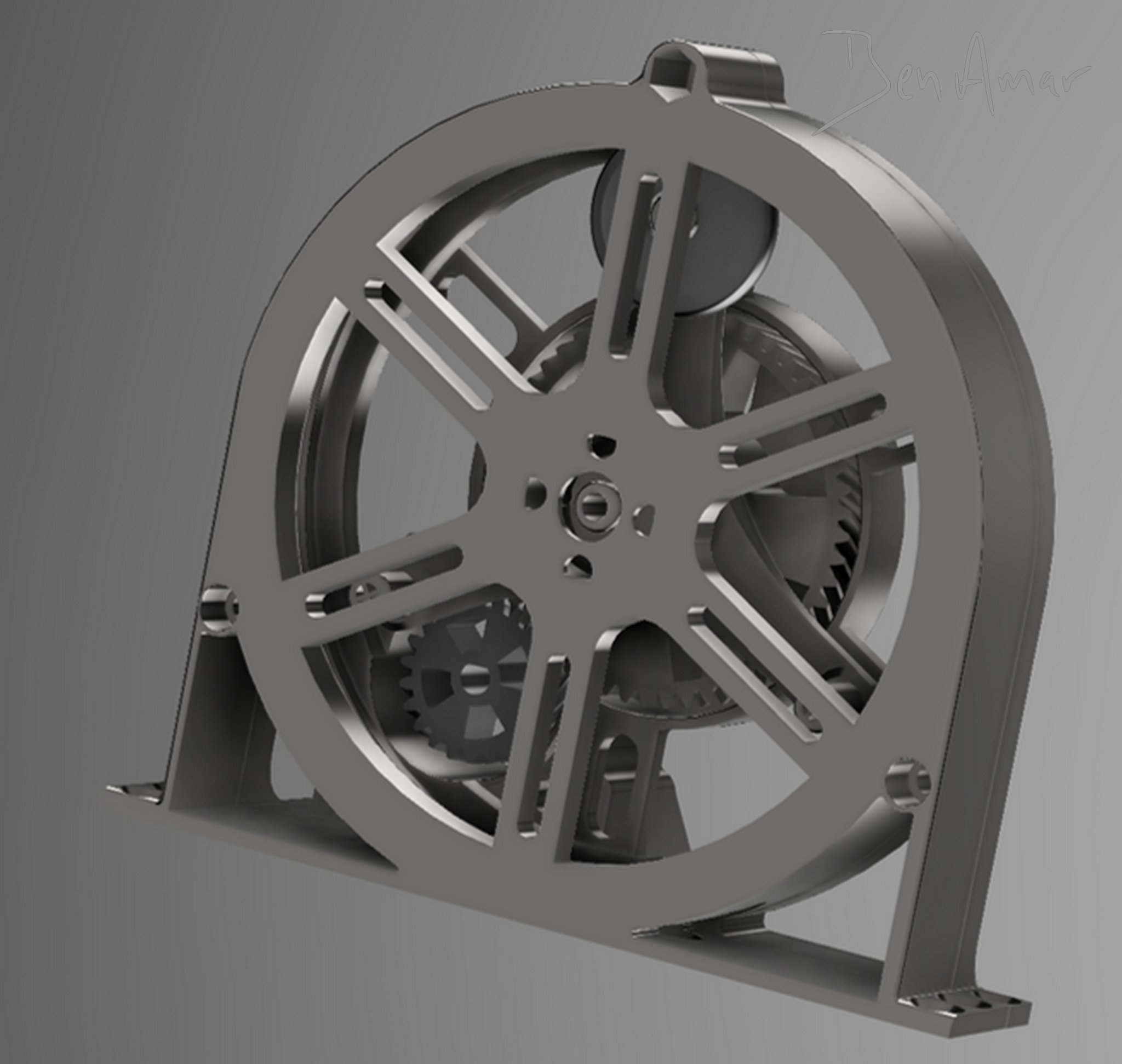
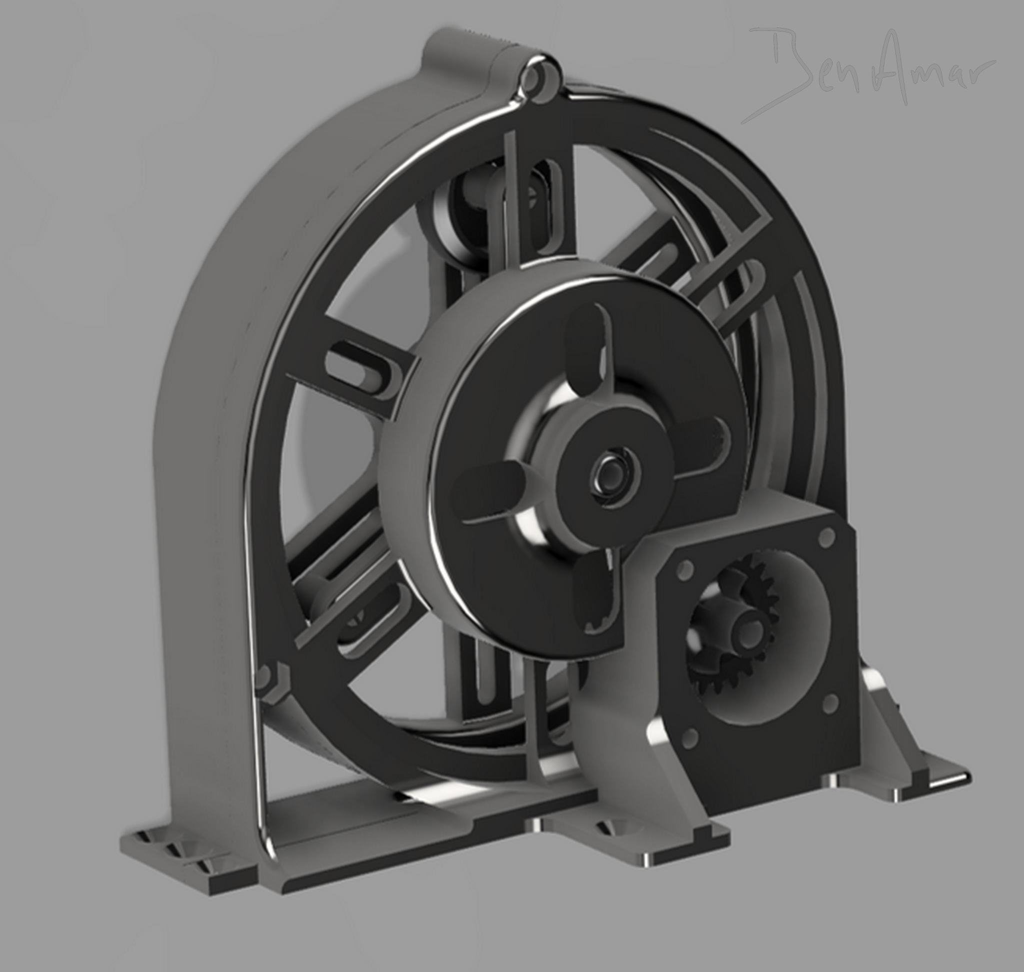
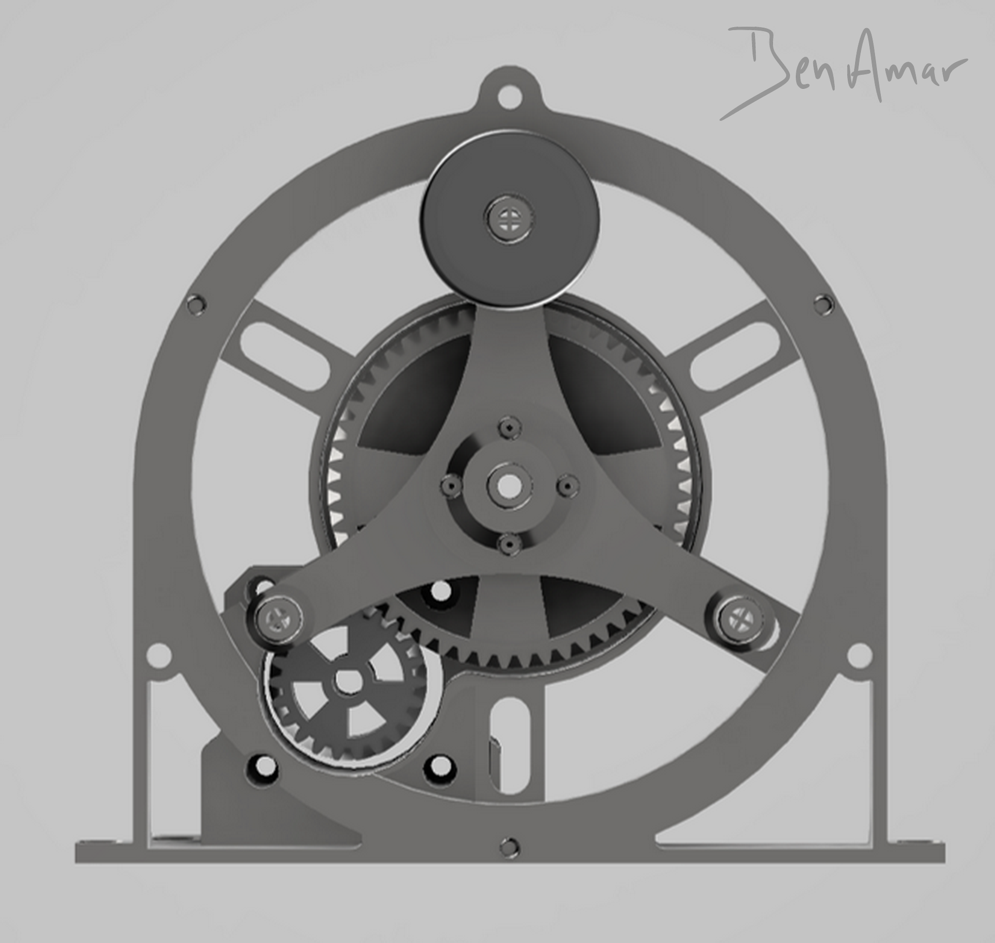
3D Rendering
Power & Control
Powered by a Nema 17 type (0.59Nm) the torque depend on :
- The driver used
- VRef Adjustment (on the driver)
- The power supply voltage
- The Speed Requested
- The acceleration
The highest step resolution achievable with an A4988 (by setting all MS pin “High”) is: 1 step = 1.8°/16 = 0.1125° (3200 Steps for one rotor full revolution)
This resolution has two main advantages: A better acceleration to achieve the expected torque at certain speed and noise reduction while the engine is working.

To Simplify the wiring, I advise you to use an A4988 extention Board. It is existing in different versions: With One Driver connection slot or Four Driver connection slots.
-
Power Supply - 12VDC to 35VDC
Here the power supply used is 19.3V (Recovered from an old laptop)
-
Arduino Uno x1
Can be replaced with an Arduino Nano
-
Stepdown - LM2596 x1
DC/DC Voltage Converter - Input 19.3VDC output set at 9VDC
-
Stepper Driver - A4988 x1
Can be replaced by a DRV8825 if a higher torque is required.
-
Potentiometer - 2000 Ohm
Used to modulate the speed of the Stepper
-
Stepper Motor - NEMA 17 (0.59 Nm)
Code
Torque Calculation

As the lever is 4.5cm long the total torque at the extremity of the 3 arms is:
100 Ncm / 4.5 cm = 22.2 N
The Total and Maximum torque available at the extremity of the 3 arms is 22.2 N.
The torque can overcome a rolling resistance of 2.3 kg (22.2/9.8) in this configuration.
If required, it is be possible to play on several factor to reduce the rolling resistance, such as:
- Shorten the Arms (Reduce the lever)
- Modify the Diameter / Form of the Rollers
- Changing the thickness of the silicone tube
- Increasing the Reduction Ratio of the gears
Here we have used Silicone tube 8mm Outer Diameter and 6mm Inner Diameter.
The Nema 17 used here is rated 0.59Nm, its holding torque is 59Ncm.
The holding torque normally is the highest torque the stepper can produce. At 300 RPM should be around 80% of the Rated Torque. Here we have considered 45Ncm.
Stepper Motor torque is tenflod by a gear box, the ratio is 0.41 as the driving gear is the smallest.
The Torque available on the biggest gear would then be:
(45Ncm/0.41) = 109 Ncm
Due to the friction, I have considered 100 Ncm Max.
// Creative Commons - www.ben-amar.com - 2021
// This Code was written for Ben-Amar.com under CC license: BY-NC-SA  (Attribution Mandatory, NonCommercial & ShareAlike)
// You must you credit "Ben-Amar.com" to remix, adapt, and build upon your work non-commercially. You must license your new creations under the identical terms.


//=======================
//======== CONTANTS ====
//=======================

const int stepPin = 4;            // stepPin for Stepper Driver
const int dirPin = 5;             // Direction pin for Stepper Driver
const int enPin = 3;              // Enable pin for Stepper Driver (Low = enable)
const int rPin = A0;              // Potentiometer Analog Reading Pin

//=======================
//======== VARIABLES ====
//=======================

int vit;                  // Declare Variable "vit" as integer for potentiometer raw value reading
int vMap = 0;             // Declare Variable mapped speed after convertion to match with expected values
int microSec = 500;       // Declare Variable for Step duration

void setup() {

  pinMode(stepPin, OUTPUT);    //  defines stepPin as Output
  pinMode(dirPin, OUTPUT);     //  defines dirPin as Output
  pinMode(enPin, OUTPUT);      //  defines enPin as Output
  pinMode(rPin , INPUT);       //  defines rPin as Input for analog reading

}

///=======================
//========= MAIN LOOP ====
//========================

void loop() {

  digitalWrite (enPin, LOW);              // Enable the Driver and the step motor (Holding Torque is ON if Enable)
  digitalWrite(dirPin, HIGH);             // Give the driver the expected direction
  for (int j = 0; j < 100; j++) {         // Stepper rotation Main for Loop
    vit = analogRead (A0);                // Reading the Potentiometer value
    vMap = map(vit, 0, 1023, 30, 250);    // Convert the value of the potentiometer in the range of speed expected for the engine
    for (int i = 0; i < 10000; i++) {     // Stepper Motion SubLoop (With acceleration)
      digitalWrite(stepPin, HIGH);        // Set the Value of stepPin at 1
      delayMicroseconds(microSec);        // Delay of define microSec
      digitalWrite(stepPin, LOW);         // Set the Value of stepPin at 0
      delayMicroseconds(microSec);        // Delay of define microSec
      if (microSec > vMap) {              // SPEED MODULATION LOOP - Speed Comparison (microSec will Move toward vMap value in this loop)
        microSec --;                      // SPEED MODULATION LOOP - If (microSec > vMap) microstep will decrement of "1"
      }                                   // SPEED MODULATION LOOP - This will occur at each iteration of the sub loop until statement is false
      else if (microSec < vMap) {         // SPEED MODULATION LOOP - If (microSec < vMap) microstep will increment of "1"
        microSec ++;                      // SPEED MODULATION LOOP - This will occur at each iteration of the sub loop until statement is false
      }                                   // SPEED MODULATION LOOP - If Both statement are false, nothing happens, speed is not modulated
    }                                     // End of Stepper Rotation Sub Loop
  }                                       // End of Stepper Rotation Main Loop
}
References
Peristaltic Pump
- Working Principle on Wikipedia: https://en.wikipedia.org/wiki/Peristaltic_pump
Stepper Nema 17 & Stepper Driver
- Stepper on Wikipedia: https://en.wikipedia.org/wiki/Stepper_motor
- Stepper Motor Basics: https://www.controleng.com/articles/stepper-motor-torque-basics/
- Stepper Motor Basics: https://www.geckodrive.com/support/step-motor-basics.html
- Torque Curve Explaination: https://www.orientalmotor.com/stepper-motors/technology/speed-torque-curves-for-stepper-motors.html
- Torque Curve Explaination: https://www.linearmotiontips.com/stepper-motor-torque-speed-characteristics-explained/
- Tutorial for Stepper & A4988: https://howtomechatronics.com/tutorials/arduino/how-to-control-stepper-motor-with-a4988-driver-and-arduino/
- Driver DM8880: https://www.pololu.com/product/2133
- Driver A4988: https://www.pololu.com/product/1182
- Vref Adjustment: https://forum.arduino.cc/t/update-current-adjustment-for-motor-drivers-drv8825-a4988/400151
- Vref Adjustment A4988: https://ardufocus.com/howto/a4988-motor-current-tuning/
- Vref Adjustment A4988: https://e3d-online.dozuki.com/Guide/VREF+adjustment+A4988/92
Lever & Torque Calculation
- https://www.engineeringtoolbox.com/levers-d_1304.html
- http://www.comfsm.fm/~dleeling/physics/torque.html
Human Ear Frequency Range:
- https://en.wikipedia.org/wiki/Hearing_range